
Technology brings a change in our daily life with the Internet, Cloud, Mobile phone, etc. However,...
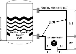
Another installation method for level measurement using a Differential Pressure level transmitter is by utilizing the diaphragm seal plus capillary tube. To determine the calibrated range for the Differential Pressure level transmitter, the filling fluid density within the capillary must be taken into account in the calculation since the fill fluid also creates hydrostatic force exerting both the DP level transmitter ports.
The density of fill fluid must be known, and the information could be obtained from manufacturer specifications.
The example below describes the calculation in determining the calibrated range for Differential Pressure level transmitter with a capillary tube.
Differential Pressure Level Range Calculation
Sample Process Data
Process fluid density = 0.96 g/cm3
Fill fluid density = 1.05 g/cm3
100% from Process Connection (h) = 4 m = 4,000mm
Height Difference between Process Connection (h2) = 5 m = 5,000mm
When level at 0% = 4mA
∆P at 0% level
∆P = P1 – P2
P1 = 0 mmH2O
P2 = 1.05 x 5,000 = 5,250 mmH2O
Therefore Range at 0% is
P1 – P2 = 0 – 5,250 = -5,250 mmH2O
When level at 100% = 20mA (Right Image)
∆P at 100% level
∆P = P1 – P2
P1 = 0.96 x 4000 = 3,840 mmH2O
P2 = 1.05 x 5,000 = 5,250 mmH2O
Therefore ∆P at 100% is
P1 – P2 = 3,840 – 5,250 = -1,410 mmH2O
Scaling to set to Differential Pressure Transmitter
0% to 100% = -5,250 ~ -1,410 mmH2O